
Different Types of Pipe Flanges
Different Types of Pipe Flanges
What is the purpose of Flanges?
Flanged fittings perform functions similar to other fittings of the same type. The major difference is their method of connection. The connection joint for flanged fittings is made by bolting two specially designed metal surfaces together. A gasket to prevent leaks is sandwiched between the two surfaces.
How is a flange connected?
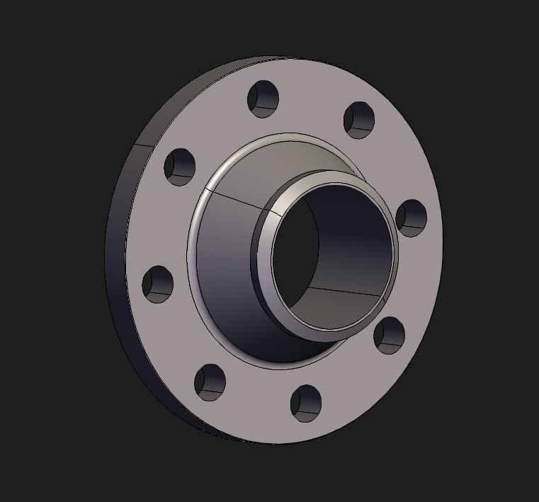
This can be illustrated with the help of a 3D model.
Equipment to Flange
- All the equipment is manufactured with nozzles.
- At the end of the nozzle, it is flanged.
- A flange will be connected to the flange end of the pipe.
- See the image below.

Valve to Flange connection
- Same as Equipment, the valve has one side with a flange.
- The same flange is connected to the pipe side flange.
- In between gaskets is a sandwich to avoid leakage in the Piping System.
- The image below can be used for reference.

Flange Faces
- The surface of the flange, nozzle, or valve’s mating surface is called the face.
- Typically, the face is machined to provide a smooth surface.
- When two flanges are bolted together with a gasket positioned in between, this smooth surface will help ensure a leak-proof seal.
Three types of faces
1. Raised Face
- This type is the most common face type in use.
- This flange face assures a positive grip with the gasket.
- On the mating surface, there is a raised face on the flange.
2. Flat face
- As the name implies, flanges with flat faces are those that have a flat, level connecting surface.
- Forged steel flanges with a flat face flange are commonly .
- Using a flat face flange will assure full surface contact, thereby reducing the possibility of cracking the softer cast iron.
3. Ring-Type Joint
- This type of flange is costly and more efficient.
- The ring-type joint does not use a gasket to form a seal between connecting flanges.
- Instead a round metallic ring is used that rests in a deep groove cut into the flange face.
- The donut-shaped ring can be oval or octagonal in design.
- As the bolts are tightened, the metal ring is compressed, creating a tight seal.
Flange Rating
- Defined as the maximum pressure allowed by the pressure piping code for the specific temperature at which the flange will be operating.
- Flanges and nozzles are sized according to pressure ratings established by the American National Standards Institute (ANSI).
- Rating represents as follows.
- Forged steel flanges: 150#, 300#, 400#, 600#, 900#, 1500#, and 2500#.
- Cast iron flanges have pound ratings of 25#, 125#, 250#, and 800#.
- Ratings are also used to establish the outside diameter and thickness of a flange.
- Typically, as pound ratings increase, so will the flange’s diameter and thickness.
Please read the article below to learn how to select a flange.
Different Types of Flanges
Flanges have been designed and developed to be used in a myriad of applications. Each one has its own special characteristics and should be carefully selected to meet specific function requirements.
The different types are
- Weld Neck
- Socket Weld
- Slip on
- Lap Joint
- Threaded
- Orifice
- Blind
Some Facts
- Flanges are primarily used where a connecting or dismantling joint is needed, joining pipe to fittings, valves, equipment, or any other integral component.
- Flanged connections are preferred over threaded connections because threading large-bore pipe is not an economical or reliable operation.
Welding Neck (WN) Flange
- The welding neck flange (or more commonly “weld neck” flange).
- Weld neck flanges are attached to the adjoining pipe with a circumferential butt weld.
- Because the ID of heavy schedule pipe may be smaller than the bore of a weld neck flange, it is important to ensure that the bore of the flange matches the ID of the adjoining pipe.
- If a shoulder is present inside the flange due to the bore being smaller than the pipe, turbulence could result from high velocities.
- If the velocities were very high, erosion could result, but this does not seem to be a common problem.
Socket Weld (SW) Flanges
- Socket weld flanges have a shoulder on the inside of the flange that serves as a reference to determine the depth at which the pipe is welded to it.
- They are made by pushing the pipe end into the flange until it bottoms out against the shoulder, then retracting the pipe 1/8 inch before

Socket Weld Flange welding it in place.
- This procedure was first used to decrease cracking caused by thermal stresses in stainless steel superheaters, but it has since become standard practice for installing all socket weld flanges.
- An internal weld bead may be used to seal the annulus between the pipe OD and the socket ID.
- Occasionally, the annulus between the pipe OD and the socket ID is sealed using an internal weld bead.
- Although this gives the flange assembly more strength as well, normal industrial applications do not frequently employ this technique.
- Although it should be mentioned that the clearance available for performing such a weld on small diameter pipes may limit the ability to execute it, one may see the significance of the internal weld for pharmaceutical, food and beverage, and some chemical applications.
Slip-On (SO) Flanges
- This flange is essentially a ring that is fitted over the pipe end, with the flange face protruding sufficiently from the pipe end to allow for

Slip On Flanges a weld bead on the inside diameter.
- The ODs are also welded to the backside of the flange.
- Slip-on flanges have a cheaper material cost than weld neck flanges and are easier to align.
- For this reason, they are popular among some engineers and contractors, but they are not as sturdy as weld neck flanges.
- Because of their lesser strength, they are only available in sizes up to 2½ in and 1500 lb.
- They are not available in 2500 pound quantities.
- Most requirements limit the usage of slip-on flanges to 300 pounds.
Lap Joint (LJ)
- Lap joint flanges use a stub end that is welded to the pipe.
- A ring flange fits loosely around the stub end, permitting easy flange alignment and joint disassembly.

Lap Joint Flanges - This obviates the need to provide careful alignment of the bolt holes.
- The short length stub ends are manufactured in accordance with MSS SP-43 and are available in all three types.
- Long length stub ends are manufactured in accordance with ANSI B16.9 and are only available for Types A and B.
- Lap joint flanges are available in up to 2500 lb pressure class.
- In addition to the ability to ease alignment and disassembly, another advantage of these flanges is the low cost of using them in corrosion resistant pipe construction.
- Low-cost carbon steel flanges may be used with stainless steel or other high alloy hubs to reduce the cost of the flange assembly.
Threaded or Screwed Flanges

- These flanges are only suitable for low-pressure systems without temperature cycles that could cause the threads to loosen.
- The flange comes with a tapered internal thread that the pipe screws into.
- Threaded flanges are used in applications where hot work (welding, burning, and grinding) is undesirable.
- To prevent leaking, they are occasionally backwelded (seal welded), just like other threaded fittings.
- This is obviously just for usage in situations where disassembly is not required.
- Furthermore, no credit is given for increased strength when a threaded fitting is backwelded.
Orifice Flanges
- The orifice flange is a specific sort of flange that always comes in pairs.
- These flanges are used to determine the pressure drop across a given orifice.
- The orifice is carefully tailored for the predicted flow and fluid properties.

Orifice Flanges - It is positioned in the center of a plate that is inserted between the flange faces.
- These flanges are never less than 300 pounds, with an increase in flange thickness to accommodate a radial hole that extends from the flange OD to the flange bore.
- The inside edge of the hole must be square with the pipe bore and clear of burrs.
- The exterior edge of the hole is threaded, allowing a tubing bushing to be attached.
- A manometer or pressure differential device can then detect the pressure difference across the orifice, allowing the flow to be estimated.
- Jack screws are also provided to help spread the flanges, allowing the orifice plate to be removed more easily.
- Installation condition
- The locations of the orifice flange must always remain flooded in liquid service (a vertical drop of the fluid through the orifice flange would be incorrect).
- Typically, the orifice plate manufacturer requires straight pipe runs of at least 5 diameters upstream and 10 diameters downstream in order to minimise turbulent flow and achieve reproducible measurements.
Blind Flange
- Blind flanges are utilized when a line needs to be capped off at a flange.

Blind Flange - It is recommended to install blind flanges at the ends of headers or in areas where future tie-ins are expected.
- Blind flanges are commonly utilized for manways, and a davit is recommended for easy handling of the unbolted cover.
- ANSI B16.47 specifies blind flanges in sizes ranging from 26 to 48.