

Piping Design Process: From P&ID to Construction – A Complete Engineering Guide
Piping design is one of the most important engineering activities in an industrial plant. Whether the project involves an oil refinery, petrochemical facility, power plant, water treatment system or biogas processing plant, piping systems must be designed to transport fluids safely, efficiently and reliably.
The piping design process involves much more than connecting equipment with pipes. It is a coordinated engineering workflow that begins with understanding process requirements and continues through equipment layout, piping routing, stress analysis, material selection, 3D modelling, fabrication, construction, testing and final handover.
A properly designed piping system must satisfy process requirements while accounting for operating conditions, equipment connections, accessibility, structural limitations, maintenance requirements and applicable engineering codes.
This article explains the complete piping design process from Piping and Instrumentation Diagrams (P&IDs) to construction, including the engineering documents, design activities, software tools and technical checks involved at each stage.
What Is the Piping Design Process?
The piping design process is a systematic engineering procedure used to convert process requirements into a physically constructible piping system.
The process engineering team establishes how fluids must move through the plant, while piping engineers and designers determine how the required equipment connections can be achieved within the available plant space.
A successful piping design must address five fundamental questions:
- What must be connected? Equipment, instruments and other piping systems identified by the process design.
- What fluid will the piping carry? The fluid properties, pressure, temperature and operating conditions.
- Where should the pipe be routed? The physical routing arrangement considering layout, safety and maintenance.
- How will the piping remain mechanically safe? Wall thickness, pressure rating, flexibility, loads and supports.
- How will the piping be fabricated, installed and tested? Materials, joints, construction sequences and quality requirements.
Although piping design is often presented as a sequence of activities, actual engineering projects involve several parallel and iterative processes. Changes in equipment locations, process conditions, vendor information or structural arrangements may require modifications to an already developed piping model.
An Overview of Piping Design Workflow: From P&ID to Construction
A typical industrial piping project follows the workflow shown below.
| Engineering Phase | Major Activities | Key Output |
|---|---|---|
| 01 – Design Inputs | P&ID, Line List, PMS, Equipment Data | Established Design Requirements |
| 02 – Layout Development | Equipment Arrangement, Piping Routing, 3D Modelling | Coordinated Physical Layout |
| 03 – Design Verification | Stress Analysis, Pipe Supports, Model Reviews | Reviewed Piping Design |
| 04 – Construction Preparation | Isometrics, MTO, Procurement, Fabrication | Materials and Fabrication Deliverables |
| 05 – Site Execution | Erection, Inspection, Testing, Commissioning | Installed and Documented System |
These activities frequently overlap. For example, stress analysis may start before detailed 3D modelling is complete, and long-lead piping materials may be purchased before the final isometric drawings are issued.
The following sections explain each activity in detail.
Step 1: Understanding the P&ID
- The Piping and Instrumentation Diagram, commonly called a P&ID, is one of the primary engineering inputs for piping design.
- A P&ID represents the functional arrangement of process equipment, pipelines, valves, instruments and control systems within a plant.
- It explains how the system must operate, but generally does not establish the physical routing, exact pipe lengths or geographical positions of piping components.
For example, a P&ID may show a centrifugal pump connected to a storage tank through a suction pipeline. It may identify the pump, tank nozzle, isolation valves, strainer, instruments and connecting pipe size.
- However, it does not necessarily indicate whether the pipe should be routed above ground, along a pipe rack or around adjacent equipment.
- That physical arrangement is developed during piping layout engineering.
Important Information Obtained from a P&IDThe piping design team reviews:
- Equipment identification numbers and connections.
- Pipeline numbers, sizes and service descriptions.
- Piping specification or material class references.
- Valves and their functional requirements.
- Flow direction and process connections.
- Instruments and control valve assemblies.
- Drains, vents and utility connections.
- Insulation, heat tracing or other special requirements.
- Tie-in points and battery-limit connections.
- Notes describing operational or maintenance requirements.
The designer should also review the relevant P&ID revision and ensure that unresolved process questions are clarified before committing to detailed routing.
Typical Errors During P&ID InterpretationCommon errors include missing isolation valves, incorrect line sizes, overlooked branch connections and incorrect nozzle identification.
For example, if a suction strainer shown on the P&ID is omitted from the piping model, the resulting isometric drawing may not represent the required process arrangement.
This can cause material shortages, drawing revisions and construction delays.
Engineering principle: Every required piping component identified in the P&ID must be appropriately represented in the detailed design, while any differences must be reviewed and formally resolved.

Step 2: Establishing the Piping Design Basis
Before detailed modelling begins, the project must establish the technical requirements governing piping design.
These are recorded through a combination of design-basis documents, process data sheets, piping material specifications, line lists and applicable codes.
Design Conditions
The piping engineer must understand the relevant design and operating conditions, which may include:
- Design pressure and temperature.
- Normal operating pressure and temperature.
- Fluid composition and corrosiveness.
- Minimum design temperature.
- Thermal expansion and contraction.
- Potential vibration and dynamic loading.
- External environmental and mechanical loads.
- Insulation and heat-tracing requirements.
The process design team normally establishes the process requirements, while piping, materials and mechanical engineering disciplines apply them to the mechanical design.
Design pressure and temperature should not be assumed to be identical to normal operating conditions. They must be obtained from the approved project design basis.
Piping Material Specification
A Piping Material Specification (PMS) establishes the acceptable piping materials and components for defined services and conditions.
Depending on the project, it may specify:
- Pipe material and dimensional requirements.
- Pipe wall thickness or schedule.
- Fittings and branch connections.
- Flange types and pressure classes.
- Valve construction and material requirements.
- Gaskets and bolting.
- Corrosion allowance.
- End connections and special component restrictions.
For example, a carbon steel utility-water line and a stainless steel chemical-process line may require different piping material classes.
Why this stage matters: Incorrect material selection can lead to corrosion problems, pressure-boundary failures, unnecessary project costs or incompatibility between connected components.
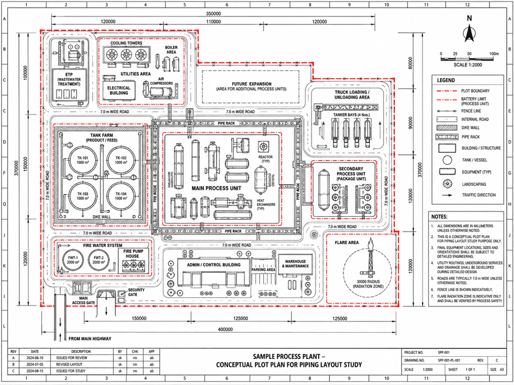
Step 3: Equipment Layout and Plot Plan Development
Once the main process connections and design requirements are established, the physical arrangement of equipment must be developed.The equipment layout identifies where machinery, vessels, tanks, exchangers and other plant components will be positioned.
This is one of the most influential activities in piping design because equipment locations determine the available routing space.
Major Considerations in Equipment Arrangement
- Accessibility: Operators must be able to reach valves, instruments and equipment requiring regular operation.
- Maintenance: Adequate space must be available for removing pumps, heat exchanger bundles, motors and other maintainable components.
- Safety: Equipment separation, emergency access and hazardous-area requirements must follow applicable project criteria.
- Piping connectivity: Equipment should be arranged with consideration for routing feasibility, hydraulic requirements, thermal flexibility and expected piping loads.
- Structural coordination: Pipe racks, platforms, foundations and supporting steel must accommodate the piping arrangement.
- Construction access: Equipment and piping must be installable using available lifting equipment and practical construction sequences.
Practical Explanation
Consider a plant with multiple pumps connected to a common discharge header.
Positioning the pumps in a coordinated arrangement may simplify header routing, improve access and reduce unnecessary pipe bends.
However, equipment arrangement cannot be optimized for piping length alone. Maintenance, hydraulic performance, safety and equipment-specific requirements may be more important.
Step 4: Piping Layout and Routing Design
Piping routing converts the process connections shown on P&IDs into a physical arrangement. This stage determines the actual pipe path between equipment connections, considering elevations, direction changes, supports, accessibility and surrounding structures.
A piping designer must develop a route that is mechanically suitable, operationally effective and practical to manufacture and install.
Principles of Effective Piping Routing
- Minimise unnecessary complexity: Avoid unnecessary elbows, offsets and excessive routing distances where practical. Additional components can increase pressure loss, fabrication effort and material requirements.
- Maintain operational accessibility: Manual valves, instruments, strainers and other operational components should be accessible for inspection and maintenance.
- Consider thermal expansion: Piping exposed to temperature variations can expand or contract. Routing should provide suitable flexibility rather than unnecessarily restricting thermal movement.
- Provide adequate clearance: Pipelines must maintain project-specified clearance from equipment, structural members, walkways and other piping systems.
- Account for drainage and venting: Routing elevations, low points and high points must support applicable process, maintenance and testing requirements.
- Consider fabrication and erection: Complex routing may be theoretically possible but difficult to manufacture, transport, weld or install.
Equipment-Specific Routing Considerations
- Pump piping: Pump suction piping requires attention to hydraulic performance, nozzle loads, accessibility and suction conditions. Depending on the pump arrangement, additional considerations may include suction-line geometry, air-pocket prevention and eccentric reducer orientation.
- Heat exchanger piping: Adequate space must be reserved for maintenance, bundle removal, valve operation and thermal movement.
- Tank piping: Tank piping arrangements require consideration of nozzle orientations, equipment movement or settlement, isolation requirements and available support locations.
- Pipe rack piping: Pipe rack design involves routing corridors, tier elevations, structural loading, line spacing and provision for future expansion where specified.
The most effective route is not necessarily the shortest route. It is the arrangement that satisfies the combined requirements of safety, operation, mechanical integrity, maintenance and construction.
Step 5: Developing the 3D Piping Model
Three-dimensional modelling transforms the proposed piping layout into a coordinated digital representation of the plant. Modern engineering projects commonly use software such as AutoCAD Plant 3D, AVEVA E3D, Hexagon Smart 3D and other plant design applications.
The purpose of 3D modelling is not simply to create a visual representation. It also supports multidisciplinary coordination and the preparation of engineering deliverables.
Typical Activities During 3D Modelling
The modelling team may perform the following activities:
- Establish the project coordinate system and modelling standards.
- Model equipment using approved dimensions and vendor information.
- Position equipment nozzles at the correct coordinates and orientations.
- Configure the approved piping specifications.
- Route pipelines according to P&IDs and engineering requirements.
- Insert valves, fittings, flanges and specialty components.
- Coordinate piping with civil, structural, electrical and instrumentation models.
- Incorporate supports and reserved maintenance spaces.
- Review geometry, connectivity and component data.
- Prepare the model for drawing and material extraction.
Example: Modelling a Pump Discharge Pipeline
- Consider a pump identified as P-101 that transfers process water to a storage tank.
- The P&ID identifies the pump discharge connection, isolation valve, non-return valve, pipeline size and destination tank.
- During 3D modelling, the designer must determine the actual equipment nozzle position, select components from the approved specification and create a suitable route.
- The model must also account for maintenance access, pipe support locations, nozzle loading, surrounding equipment and constructability.
- The completed pipeline model becomes a source for isometric drawing generation, material quantities and engineering coordination.
P&ID and 3D Model Validation
- Where the project uses an integrated design system, the piping team should check for inconsistencies between the P&ID and the 3D model.
- For example, a valve shown on the P&ID may be missing from the model, or a component may be assigned to the wrong line number.
- In AutoCAD Plant 3D, validation tools can help identify certain connectivity, component-property and P&ID-to-model discrepancies.
- However, automatic validation does not replace engineering review. Model geometry, nozzle loading, maintainability and constructability still require appropriate technical checks.
Step 6: Piping Stress Analysis and Support Design
Piping systems experience forces and moments due to pressure, weight, temperature changes, movement and external loads.
These effects must be evaluated to ensure that the system remains mechanically acceptable under relevant operating and design conditions.
Piping stress analysis is an important part of this process.
Common Loads Considered in Piping Engineering
- Sustained loads: Primarily include pressure and weight effects, subject to the applicable code’s definitions.
- Thermal displacement loads: Develop due to thermal expansion, contraction and imposed movement.
- Occasional loads: May include wind, seismic effects and other applicable occasional loading conditions.
- Dynamic loads: Can arise from vibration, pulsation, transient events and other system-specific effects.
Stress analysis is commonly performed using specialist software such as CAESAR II, AutoPIPE or equivalent tools. The analysis may evaluate piping code stresses, displacements, support reactions and loads transferred to connected equipment.
Piping Support Engineering
Supports control pipe movement and transfer loads to supporting structures.
Typical support arrangements include:
- Resting supports.
- Guides.
- Line stops.
- Anchors.
- Variable spring supports.
- Constant-effort supports.
- Hangers and restraints.
The correct selection depends on pipe geometry, loads, movement and operating conditions.
For example, a high-temperature steam line may require sufficient thermal flexibility and carefully arranged restraints. Excessive restriction can increase system loads and the forces transmitted to equipment nozzles.
Important: Not every pipeline needs a detailed computer-based stress model. The extent of formal analysis depends on the governing code, project requirements, service conditions, system complexity and engineering assessment.
Piping layout and stress engineering should work together throughout design development rather than treating stress analysis as a final approval exercise.
Step 7: Multidisciplinary Design Review and Clash Detection
Industrial piping systems share limited space with structural members, cable trays, ducts, equipment, platforms and other services.
A pipeline that appears correctly routed in isolation may conflict with another engineering discipline.
For this reason, coordinated design reviews are essential.
Types of Design Conflicts
- Physical clashes: Two objects occupy overlapping space.
- Clearance conflicts: Components do not physically intersect but violate required access or separation distances.
- Maintenance conflicts: A pipe blocks equipment removal, valve operation or inspection access.
- Construction conflicts: The final arrangement cannot be installed using the available construction sequence or lifting access.
- Engineering conflicts: A geometrically valid route produces unacceptable equipment loads, drainage problems or other functional concerns.
Model Review Activities
Common review activities include:
- Checking equipment and nozzle positions.
- Confirming routing against P&IDs.
- Reviewing accessibility and maintenance space.
- Checking pipe-support arrangements.
- Resolving civil and structural interferences.
- Reviewing safety and escape-route requirements.
- Confirming instrument and valve accessibility.
- Verifying model completeness for the intended project stage.
Many EPC projects conduct staged model reviews as the design matures. The exact percentages, approval gates and release criteria depend on the project execution plan.
A coordinated model helps prevent avoidable field modifications and costly construction rework.
Step 8: Preparation of Piping Engineering Deliverables
Once the required design checks and approvals have been completed, piping information is prepared for procurement, fabrication and construction. The principal deliverables may include piping general arrangement drawings, isometric drawings, material take-offs and support drawings.
Piping General Arrangement Drawings
General arrangement drawings represent the piping layout using plans, elevations and relevant sectional views.
They may communicate:
- Equipment positions.
- Pipe routes and elevations.
- Line identification.
- Major dimensions.
- Support locations.
- Access and clearance information.
These drawings help construction teams understand the physical relationship between pipelines, equipment and plant structures.
Piping Isometric Drawings
Piping isometric drawings represent piping arrangements in a simplified three-dimensional format.
They are widely used for fabrication, erection and material identification.
A typical piping isometric may contain:
- Line number and drawing identification.
- Pipe sizes and material specifications.
- Fittings, valves and specialty items.
- Pipe dimensions and coordinates.
- Weld locations and identifiers, where required.
- Field weld and shop weld information.
- Bill of materials.
- Fabrication and construction notes.
Isometric drawings must be checked for technical consistency before formal issue.
A model-generated isometric should not automatically be considered error-free simply because the geometry was extracted using software.
Material Take-Off and Bill of Materials
- Material take-off, commonly called MTO, identifies the materials required for a piping system.
- Typical quantities include pipes, elbows, tees, reducers, flanges, valves, gaskets and bolting.
- MTO information supports procurement planning, cost estimation and material availability assessment.
- The accuracy of material quantities depends on the maturity and completeness of the underlying engineering information.
For example, a preliminary MTO may be appropriate for budgeting or early purchasing decisions, while a later material report may support detailed construction requirements.
Step 9: Material Procurement and Fabrication
Once approved material requirements are available, the procurement team arranges the purchasing and delivery of piping components. The piping design team may support procurement by preparing technical requisitions, reviewing vendor documentation and resolving engineering queries.
Material Procurement Activities
Typical activities include:
- Finalising the applicable material specifications.
- Preparing material requisitions.
- Reviewing technical compliance of supplier offers.
- Placing purchase orders.
- Reviewing required vendor drawings and documentation.
- Performing applicable inspections.
- Receiving and identifying delivered materials.
- Maintaining traceability where specified.
Material procurement may begin before all detailed engineering activities are complete, particularly for long-lead items.
Piping Fabrication
- Fabrication involves converting approved engineering drawings and piping materials into piping assemblies or spools.
- Typical fabrication activities include material identification, cutting, fit-up, welding, dimensional checking and required examinations.
- Shop fabrication and field fabrication are planned according to transport limitations, site accessibility, available equipment and construction requirements.
For example, a long pipeline may be divided into multiple fabricated spools rather than manufactured as one continuous assembly.
Fabrication Quality Requirements
Depending on project requirements and the governing construction code, fabrication controls may cover:
- Material identification and traceability.
- Qualified welding procedures.
- Welder qualification.
- Weld examination.
- Dimensional tolerances.
- Heat treatment where required.
- Inspection documentation.
The objective is to ensure that fabricated piping corresponds to approved drawings and applicable technical requirements.
Step 10: Piping Construction and Site Installation
After the necessary equipment, structures and piping materials are available, construction teams begin installing the piping systems. Construction may involve the erection of prefabricated spools, installation of supports and completion of field connections.
Typical Piping Installation Sequence
- Verify construction drawing revisions.
- Check equipment and structural readiness.
- Confirm material and spool availability.
- Verify equipment nozzle locations and orientations.
- Install or prepare the required pipe supports.
- Position piping spools using suitable lifting arrangements.
- Perform field fit-up and welding.
- Install approved inline components.
- Complete required inspections.
- Prepare the system for testing and reinstatement.
The actual installation sequence depends on site conditions, equipment availability and the approved construction methodology.
Common Construction Challenges
- Nozzle mismatch
- The fabricated piping arrangement may not align with the installed equipment nozzle.
- Possible causes include incorrect reference drawings, equipment positioning errors, fabrication deviations or unresolved design changes.
- Inadequate installation clearance
- A completed piping spool may be difficult to move into position because adjacent structures or equipment obstruct installation.
- Material shortages
- Missing fittings, valves or specialty components may delay completion of piping systems.
- Support discrepancies
- A support may be incorrectly positioned or may interfere with equipment, structural members or the required pipe movement.
- Drawing revision conflicts
- Construction based on superseded drawings may require modifications to installed piping.
- Resolving these issues requires coordination between construction, piping engineering, quality assurance and other relevant disciplines.
- Changes should follow project-approved engineering and document-control procedures rather than being introduced informally at the site.
Step 11: Inspection, Testing and Pre-Commissioning
After piping installation, the completed system must undergo the required examination, inspection and testing activities before being placed into service. The specific requirements depend on the applicable piping code, fluid service, project specifications and regulatory obligations.
Inspection Activities
Inspection may include:
- Visual examination of completed welds.
- Dimensional and installation checks.
- Verification of materials and components.
- Review of required non-destructive examination results.
- Confirmation of supports and restraints.
- Checking specified valve orientations and accessibility.
- Verification of required fabrication and installation records.
Pressure Testing
- Pressure testing is performed to demonstrate compliance with applicable test requirements.
- Hydrostatic testing uses a suitable liquid test medium, while pneumatic testing uses a gas.
- The test method, pressure, duration, preparation and acceptance criteria must follow the governing code and approved project procedures.
- Pneumatic testing requires particular safety consideration because compressed gas stores substantial energy.
- It is incorrect to apply one universal test-pressure multiplier or test procedure to every piping system.
Pre-Commissioning Activities
Depending on the system, pre-commissioning may involve:
- Cleaning and flushing.
- Drying.
- Leak checks.
- Reinstatement following testing.
- Removal of temporary test arrangements.
- Verification of valve positions.
- Instrument and equipment readiness checks.
- Completion of applicable punch-list items.
These activities prepare the piping system for safe commissioning.
Step 12: Commissioning Support and Final Handover
Commissioning establishes whether the installed systems operate as intended under the approved startup procedures. Piping engineers may assist in resolving technical questions, checking system modifications and verifying that the installed arrangement remains consistent with approved design requirements.
During commissioning, issues may become apparent that were not identified during detailed engineering or construction.
Examples include unexpected vibration, drainage problems, thermal movement concerns and operational accessibility issues.
Any required modifications must be assessed, approved and documented.
Final Piping Documentation
The final handover package may include:
- Approved as-built drawings.
- Updated isometric drawings.
- Relevant material certificates.
- Welding and examination records.
- Pressure-test records.
- Inspection and quality documentation.
- Approved engineering changes.
- Completed punch-list and turnover documentation.
The exact requirements depend on the project and contractual handover criteria.
The piping design process is not fully complete merely because the 3D model has been issued. The engineering information must ultimately correspond to the installed and accepted piping system.
Practical Example: Designing a Pump-to-Tank Pipeline
Consider a simplified industrial water-handling system. A centrifugal pump transfers water from an intermediate vessel to a storage tank through a discharge pipeline.
For illustration, assume the following preliminary information.
These are illustrative project details, not a completed mechanical design.
Stage 1: P&ID Review
- The designer identifies the discharge line, pump and tank connections, isolation valve, check valve and any other required components.
Stage 2: Engineering Inputs
- The approved piping specification, design conditions and applicable code are identified.
- Equipment nozzle information and other vendor data are obtained.
Stage 3: Layout Development
- The pump and tank coordinates are established.
- The piping designer evaluates possible routes, access requirements and support locations.
Stage 4: 3D Modelling
- The proposed line is modelled using the approved piping specification.
- Valves, flanges, fittings and connections are placed according to the design documents.
Stage 5: Mechanical Checks
- The design is reviewed for pipe loads, flexibility, support requirements and equipment nozzle loading.
- The extent of detailed analysis is established according to engineering requirements.
Stage 6: Drawing Generation
- General arrangement and piping isometric drawings are prepared.
- Material quantities are extracted and verified.
Stage 7: Fabrication and Installation
- Approved piping spools are fabricated and installed after the necessary materials and site conditions are available.
Stage 8: Testing and Handover
- The installed system undergoes applicable inspection, testing and pre-commissioning activities.
- Approved as-built information is prepared for final handover.
This example demonstrates how a relatively simple pipeline requires coordination between process engineering, piping design, mechanical engineering, procurement and construction.
Major Documents Used During the Piping Design Process
| Engineering Document | Primary Purpose |
|---|---|
| Process Flow Diagram (PFD) | Defines major process flows and equipment relationships. |
| Piping and Instrumentation Diagram (P&ID) | Defines process connections, valves and instrumentation. |
| Piping Line List | Records important line data and design requirements. |
| Piping Material Specification (PMS) | Specifies acceptable piping components and materials. |
| Equipment Layout / Plot Plan | Establishes the physical arrangement of the plant. |
| Equipment and Nozzle Drawings | Provides connection dimensions and nozzle orientations. |
| Piping General Arrangement (GA) | Communicates piping routing and physical arrangement. |
| 3D Plant Model | Supports multidisciplinary design coordination and generation of engineering deliverables. |
| Stress Analysis Documentation | Records mechanical flexibility, piping loads and stress assessments. |
| Piping Isometric Drawings | Supports piping fabrication, material identification and site installation. |
| Material Take-Off (MTO) | Identifies piping material quantities for procurement and planning. |
| Pipe Support Drawings | Defines pipe support arrangements and construction details. |
| As-Built Drawings | Records the final installed piping arrangement, including approved site modifications. |
Applicable Codes and Standards in Piping Design
Piping projects are governed by applicable engineering codes, specifications and statutory requirements.
The selection depends on the facility type, fluid service, jurisdiction and contractual design basis.
Some widely used standards include:
| Standard | General Application |
|---|---|
| ASME B31.3 | Process piping. |
| ASME B31.1 | Power piping. |
| ASME B31.4 | Pipeline transportation systems for liquids and slurries. |
| ASME B31.8 | Gas transmission and distribution piping systems. |
| ASME B16.5 | Pipe flanges and flanged fittings. |
| ASME B16.9 | Factory-made wrought butt-welding fittings. |
| ASME B16.34 | Valves with flanged, threaded and welding ends. |
| ASTM A106 / A106M | Seamless carbon steel pipe for high-temperature service. |
| ASTM A312 / A312M | Seamless, welded and heavily cold-worked austenitic stainless steel pipe. |
These standards perform different functions. For example, a pipe material standard does not replace the requirements of a piping construction code. The governing code edition and applicable supplementary requirements must be established by the project.
Common Mistakes to Avoid in Piping Design
Even when sophisticated design software is available, piping engineering errors can occur if the underlying engineering information is incorrect or incomplete.
The following mistakes deserve particular attention.
- Beginning detailed routing without verified nozzle information: Incorrect nozzle coordinates or orientations can require extensive piping modifications.
- Using an incorrect piping specification: A wrong specification assignment can affect selected pipes, fittings, flanges and valves.
- Ignoring maintenance requirements: A pipeline may satisfy geometric routing requirements while preventing equipment removal or routine operation.
- Treating stress analysis as an afterthought: Late changes to restraint locations or routing can affect multiple engineering disciplines.
- Failing to control design revisions: Uncoordinated revisions between P&IDs, models and construction drawings can lead to discrepancies.
- Assuming automatically generated drawings require no verification: A drawing-generation system can reproduce incorrect model data consistently.
- Overlooking construction feasibility: Installation access, spool dimensions and site welding requirements must be considered during design.
- Failing to update as-built documentation: The final engineering records must reflect approved changes made during construction.
Piping Design Checklist Before Construction Release
Before releasing piping information for construction, the engineering team should complete the applicable checks.
- Latest approved P&IDs have been reviewed.
-
Line numbers, sizes and piping specifications are consistent.
-
Equipment positions and nozzle details are verified.
-
Piping routes satisfy applicable layout requirements.
-
Valves and instruments are accessible.
-
Required drainage, venting and slope provisions are addressed.
-
Thermal movement and mechanical loads have been assessed.
-
Pipe-support requirements are coordinated.
-
Relevant interdisciplinary clashes are resolved.
-
Required model and drawing reviews are complete.
-
Isometric drawings are checked against approved design information.
-
Material quantities and major components are verified.
-
Fabrication and installation requirements are addressed.
-
Outstanding technical comments are closed or formally managed.
-
Deliverables carry the correct revisions and release status.
The checklist is a general engineering reference and must be supplemented by the project’s approved checking procedures.
Frequently Asked Questions About the Piping Design Process
1. What is the first step in piping design?
The first step in detailed piping design is to understand the approved process requirements, P&IDs, design basis, line data and applicable piping specifications. These establish what the piping system must achieve before physical routing is finalized.
2. What is the difference between a P&ID and a piping isometric drawing?
A P&ID represents the functional relationship between equipment, piping, valves and instruments. A piping isometric represents a physical pipeline arrangement with dimensions, components and fabrication-related information.
3. Which software is used for piping design?
Common tools include AutoCAD Plant 3D, AVEVA E3D and Hexagon Smart 3D for plant modelling. Engineering teams may use CAESAR II, AutoPIPE or other specialist applications for piping stress analysis.
4. Is piping stress analysis required for every pipeline?
All piping systems require appropriate consideration of mechanical integrity, but the need for detailed computer-based stress analysis depends on the applicable code, project specifications, service conditions and engineering assessment.
5. What happens after 3D piping modelling?
Following model development, the design undergoes appropriate checks and reviews. The team prepares required drawings, material quantities and other construction deliverables. Procurement, fabrication and construction can then proceed according to the project’s release and execution plan.
6. What is the role of a piping designer during construction?
A piping designer may support construction by clarifying drawings, reviewing field queries, evaluating routing changes, coordinating revised models and preparing approved as-built documentation.
The most important principle in piping design is that a successful model must represent a system that can be safely operated, maintained, fabricated and constructed—not merely a pipeline that fits within the available space.


